Another hobby of mine is Airsoft – imagine paintball but with small plastic pellets. Great craic and a good way of getting in some sneaky exercise.
Most of the guns used are classed as “AEG’s” – Auto Electric Guns. A battery is used to power a motor which pulls back on a spring loaded piston through a set of gears. When the piston is released, it moves forwards and compresses air – this air is used to “fire” the plastic pellet down the barrel.
As is the same with most devices, the most common battery type used in Airsoft nowadays is the lipo battery. Great power in a small package but it has is downsides. One of those is that they can fail fairly easily in comparison to nimh batteries and when they do, the typical mode of failure is that they will go puffy and swell up. This is a good indication that the battery is on the way out or has already failed.
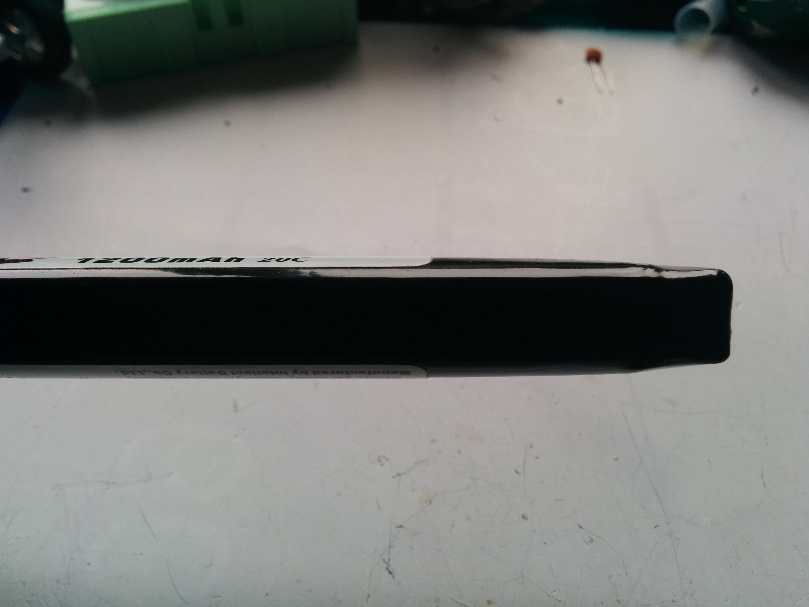
You can see the puffiness in the battery at the right hand side. Due to the gassing, it has swollen up.
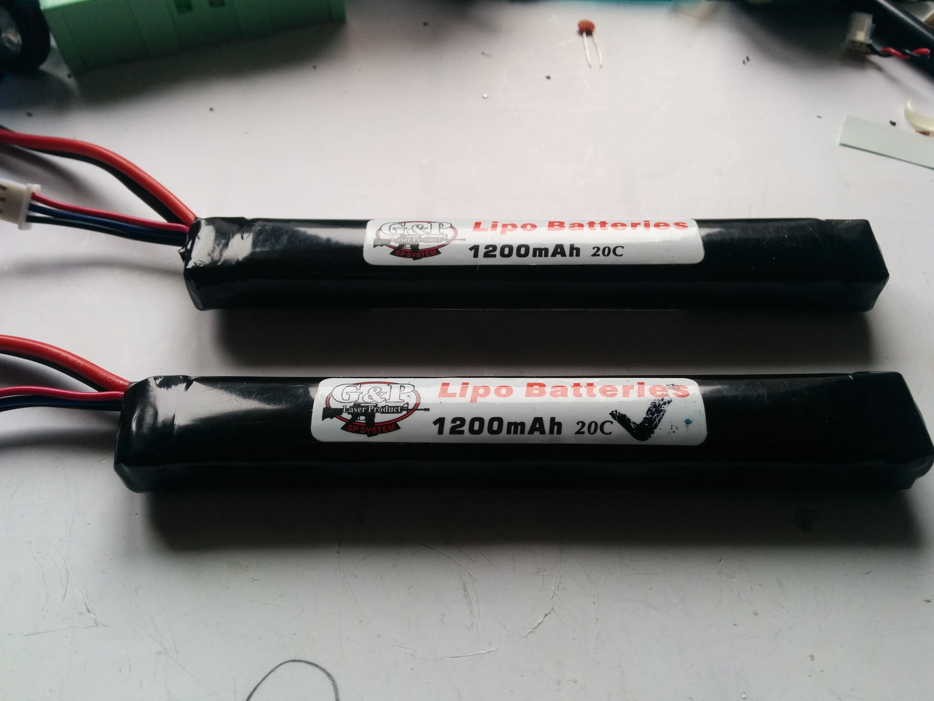
My brother also plays and two of his batteries had suffered this fate, each one looking like one of the cells in the battery had failed. The batteries in question were 1200mAh 7.4V G+P 20C lipos. Given that they were the same type of battery, I offered to combine the remaining good cell from each battery to make a “new” battery. It is important to note that this was an option due to the same cells being used in both batteries. If the cells were mismatched (different mAh rating) this would not be a good idea as it would lead to an unbalanced battery pack.
Each battery is composed of two 3.7V cells: 3.7V + 3.7V = 7.4V. These values are only the nominal values for the cells and actually can vary quite a bit from that nominal value. By testing the voltage of each cell, it should be possible to work which are the bad cells and if there are two good ones.
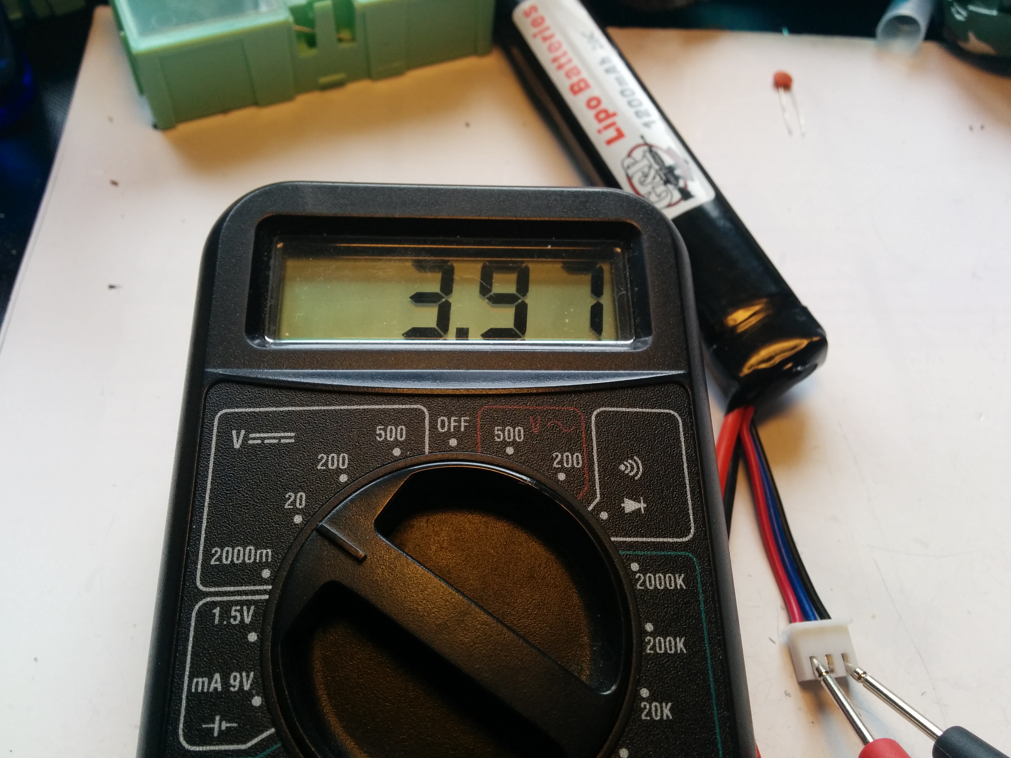
Voltage across both cells shows 3.97 when expected to be between 6.2 and 8.4

Bad cell showing 0V
Good cell showing 3.97V – same voltage as shown above to be across both cells
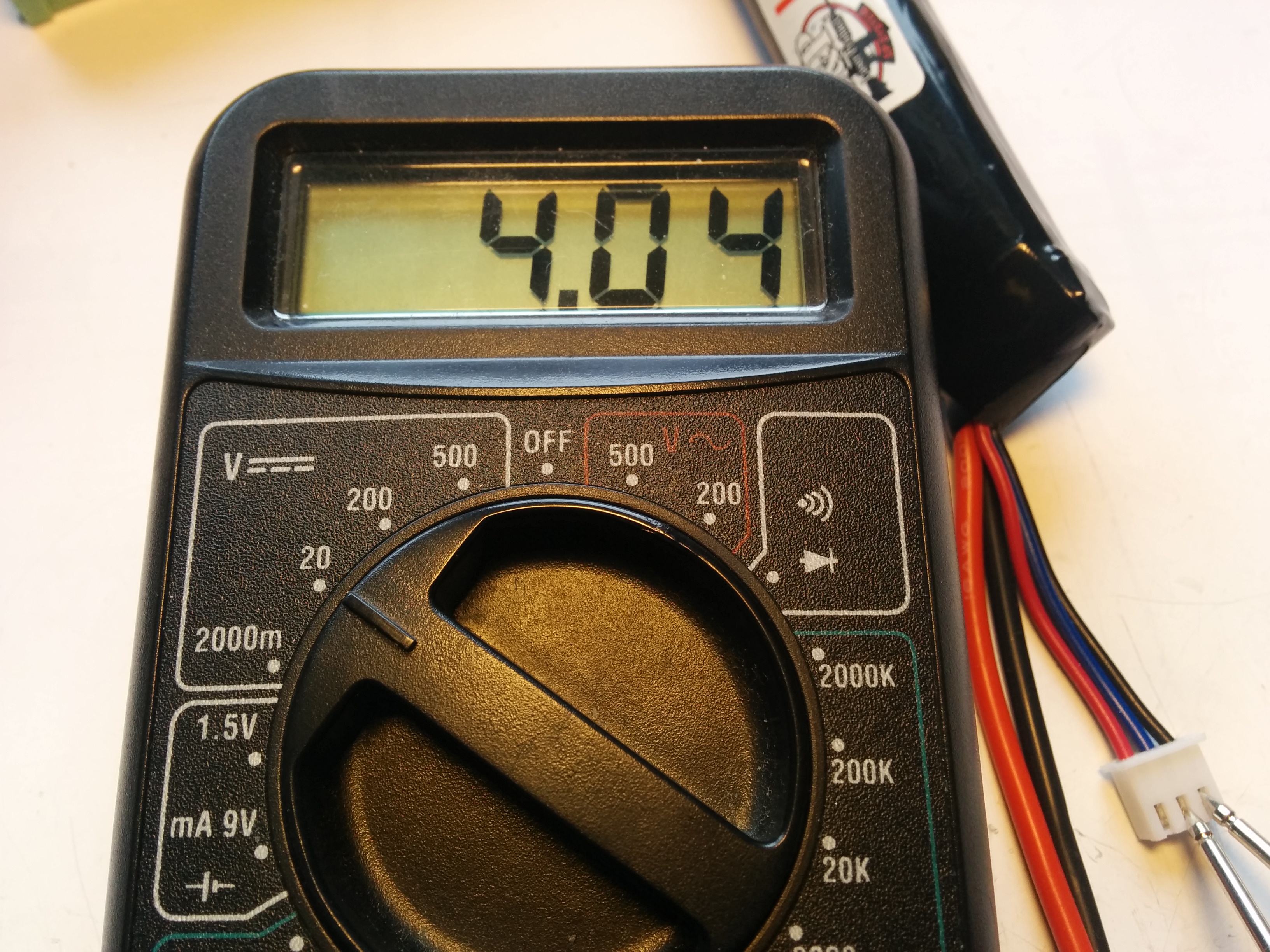
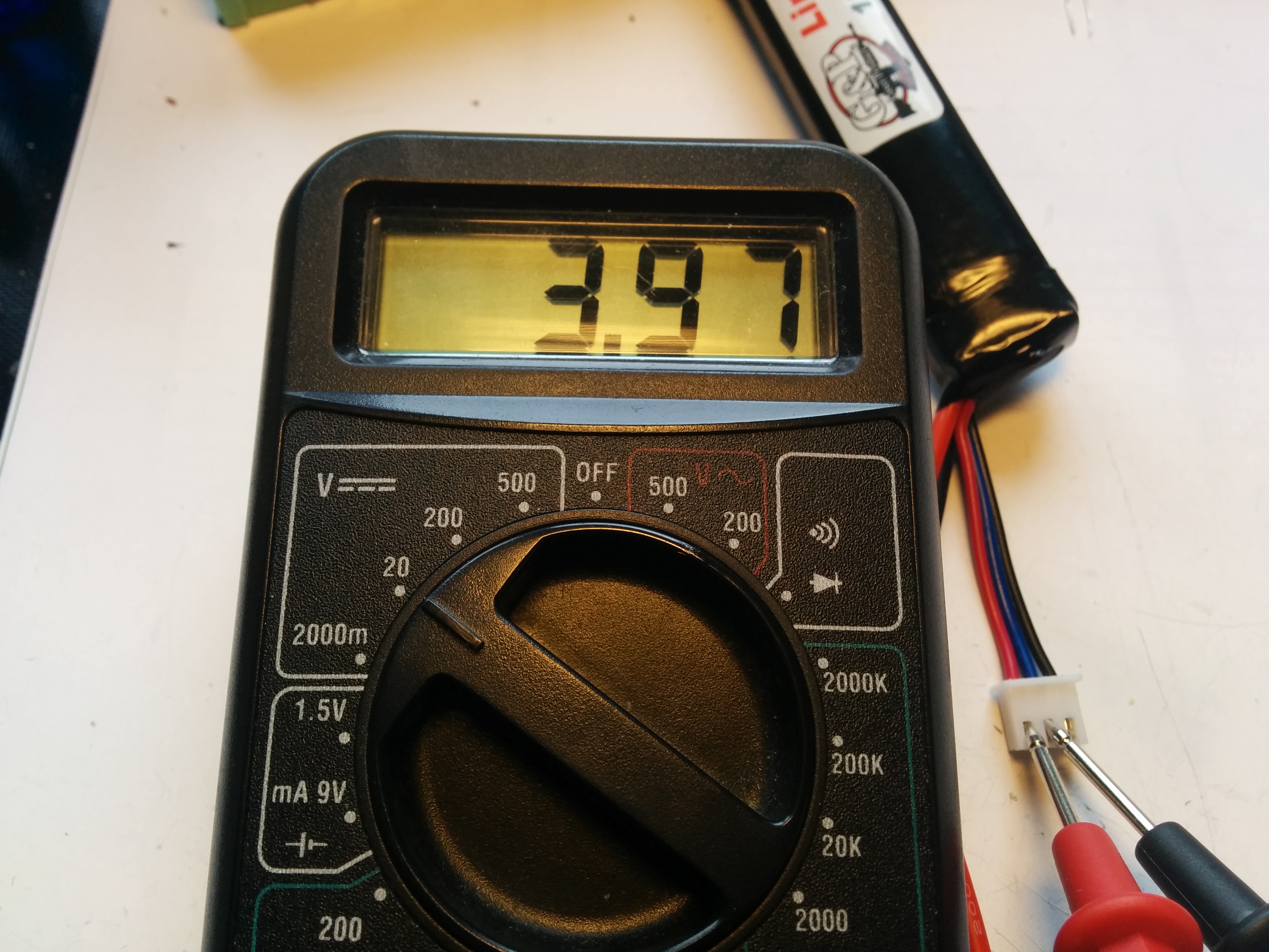
Good cell from second battery showing 4.04V
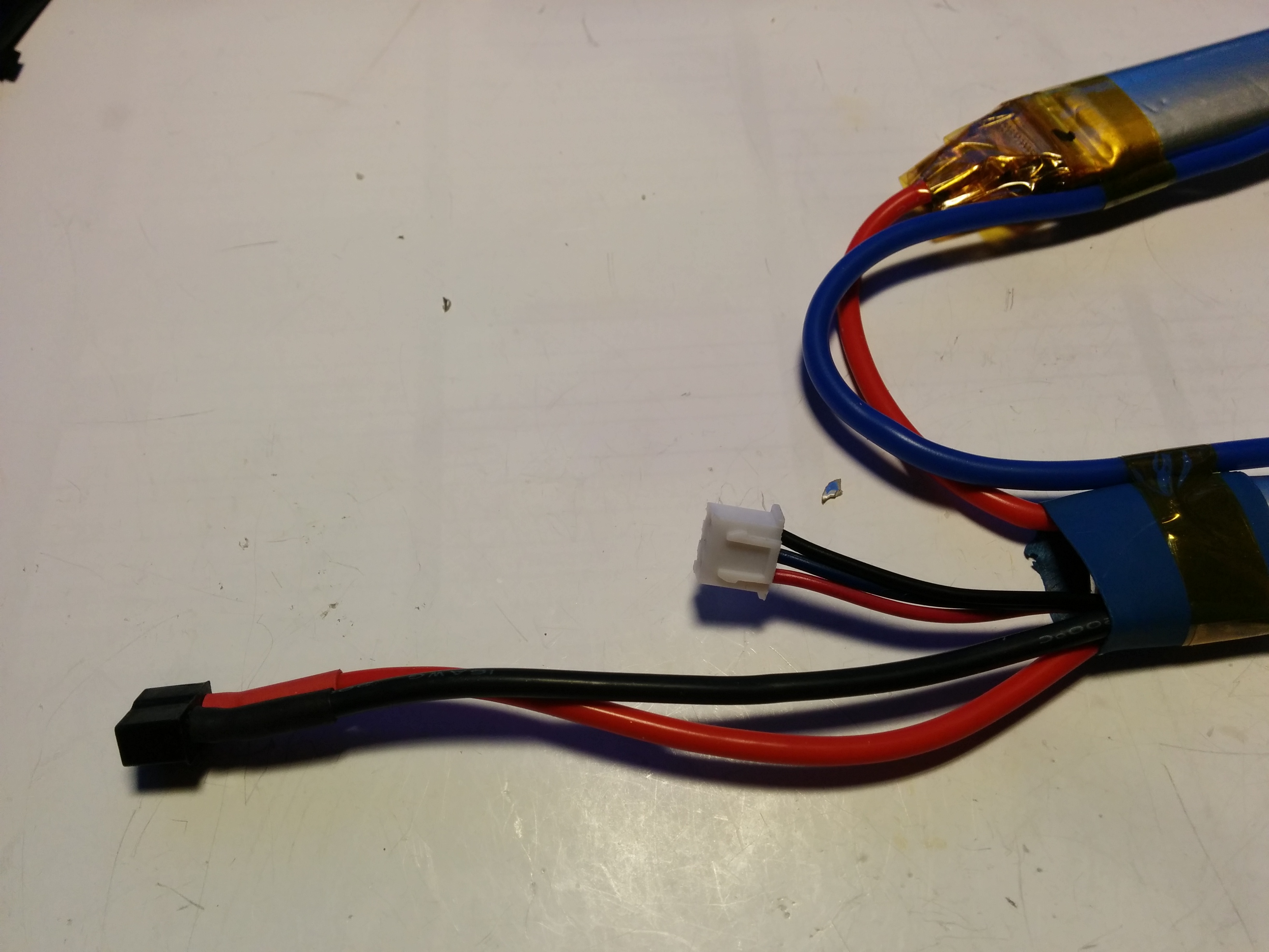
The testing of the voltages can be done via the balance lead which has connections across each of the cells as shown in the image below.
Testing the cells in the first battery showed that one cell was at 0V and one at 3.97. The second battery gave a similar 0V and 4.04V so we had two good cells! 🙂 if you look closely at the pictures above, you can see that the voltage on the good cell in each battery is measured across two different pairs on the balance lead. This implies that it should be easier to recombine the two good cells into one battery as they are naturally the two opposite halves of the battery.
Next step was to start stripping the batteries down to the separate cells. The battery is covered in a shrink wrap coating. I used a blade to carefully nick the plastic coating at one end and then tearing off the shrink wrap.
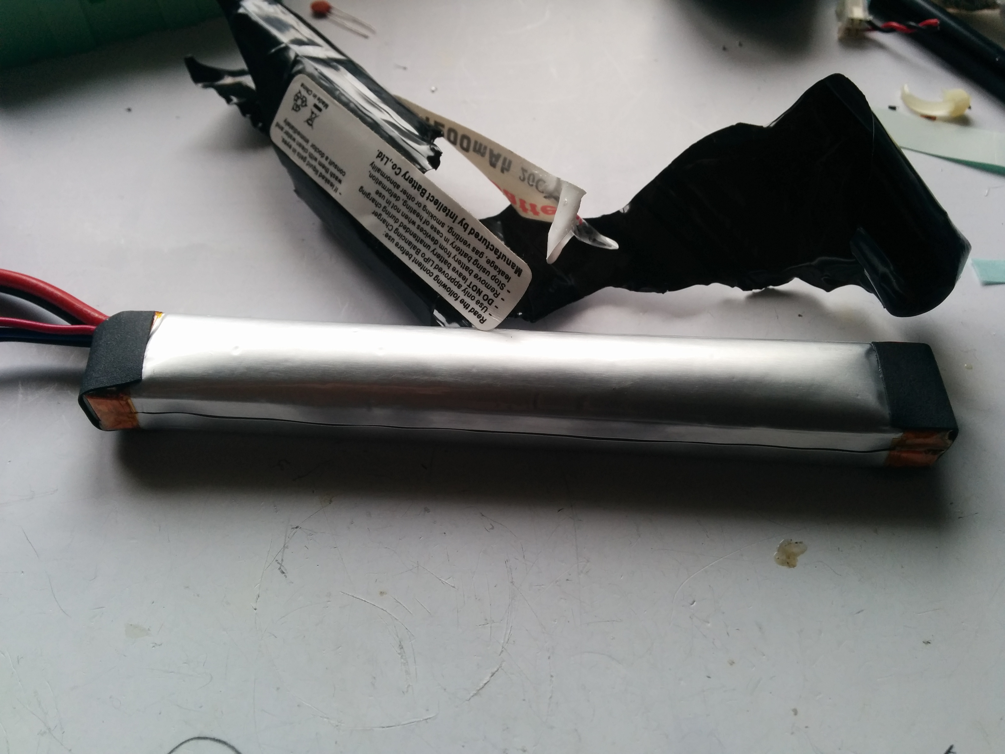

You can see the silver foil that forms the outer covering of the cell. It is very important to avoid puncturing this to prevent a fire starting. Covering both ends is a piece of thick paper and some kapton tape. The kapton tape acts as insulation to ensure there are no short circuits.
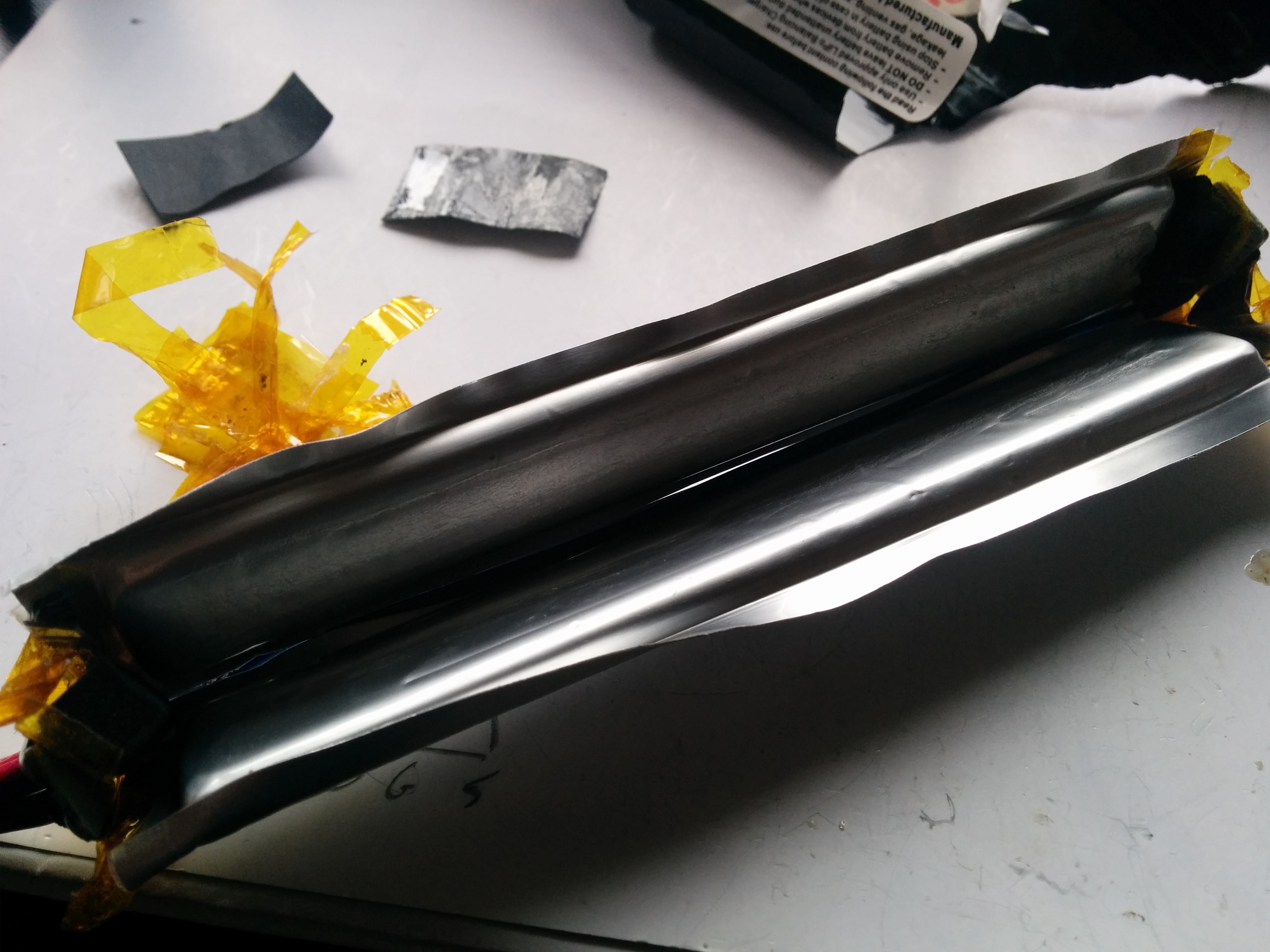
The two cells were attached together with double sided tape so I carefully prized the cells apart using a round plastic rod to rub in between the cells to break the adhesive seal of the tape. You can see that the cells were marked at one end with a “+” to denote the positive end.
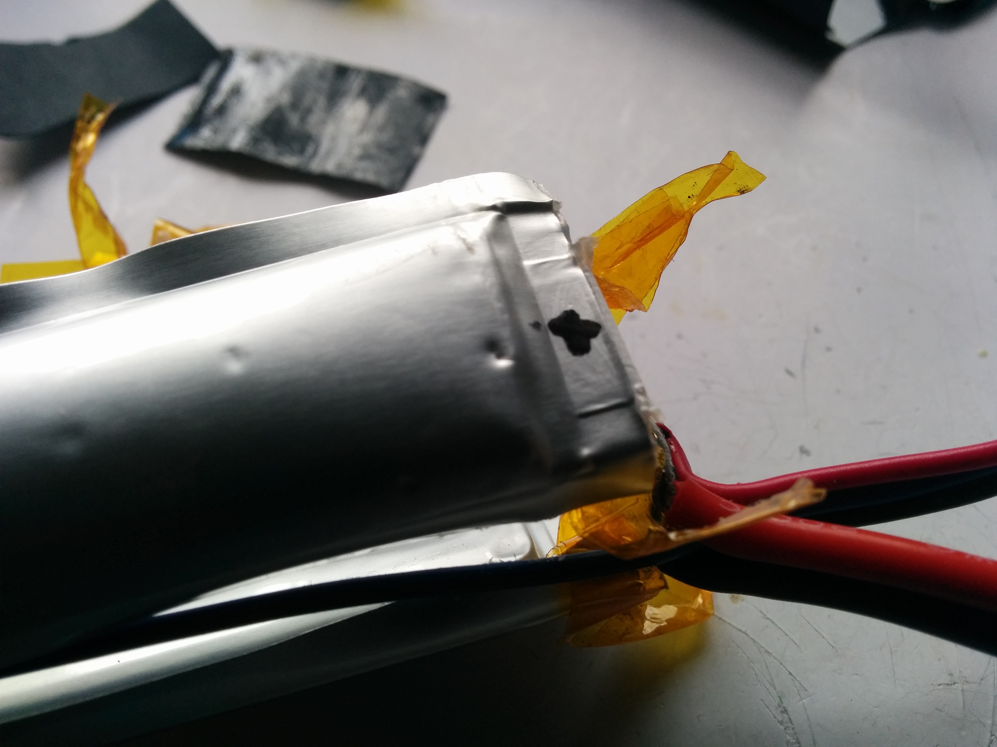
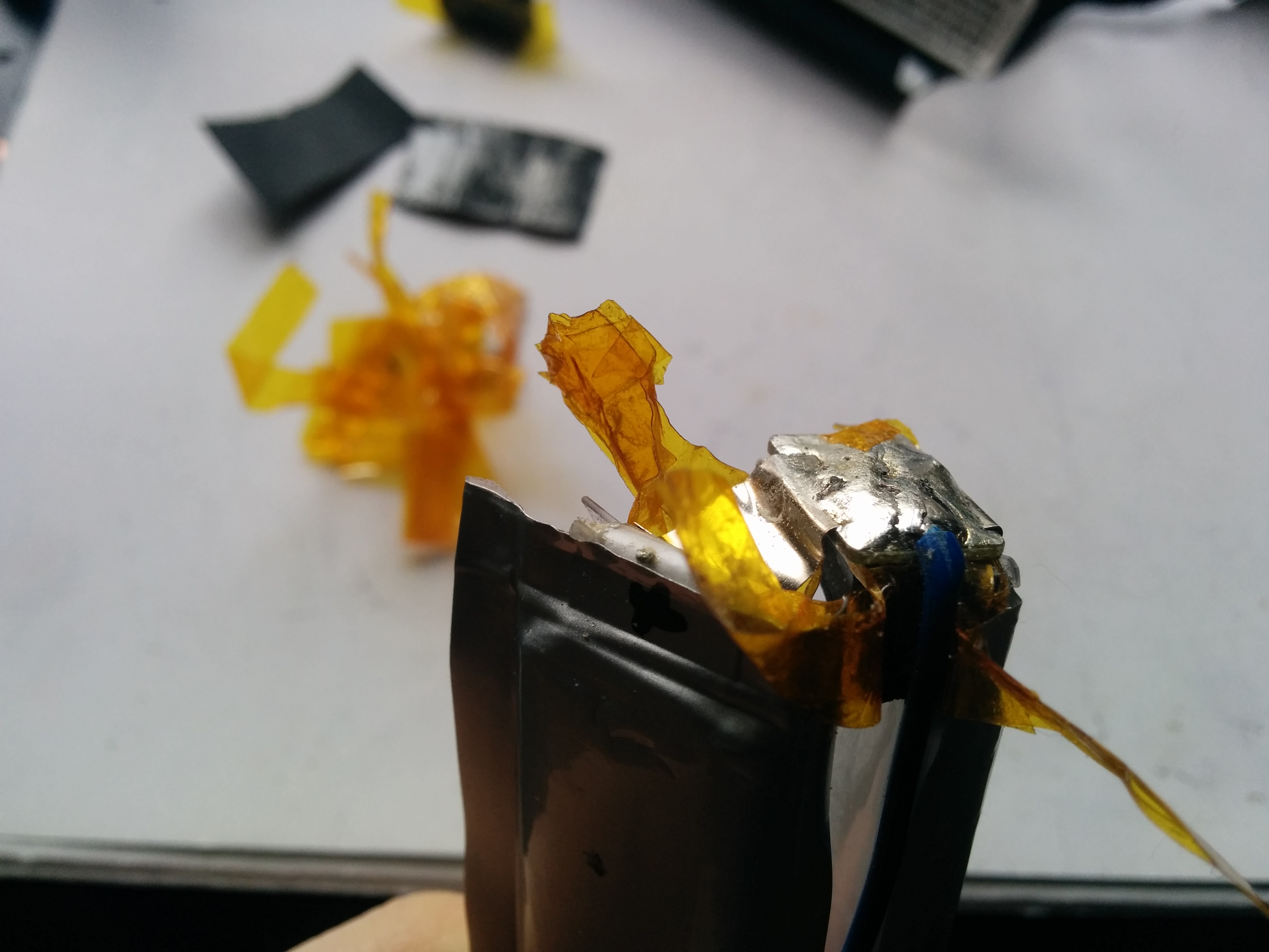
One of the cells on the second battery was already ruptured before I had removed the shrink wrap. You can see some of the lithium polymer that has oozed out and crystallized in the picture above. At this point I was thinking about stopping but as the battery hadn’t exploded in the last few months, I didn’t think it would go any further. I did however carry out the rest of the dis-assembly of that battery whilst outside and holding it over an ammo can. If there was any heat build up, indicating an imminent issue, I could simply drop the battery in the can and close the lid to reduce the air supply to the fire. I also had a fire extinguisher on standby just in case.
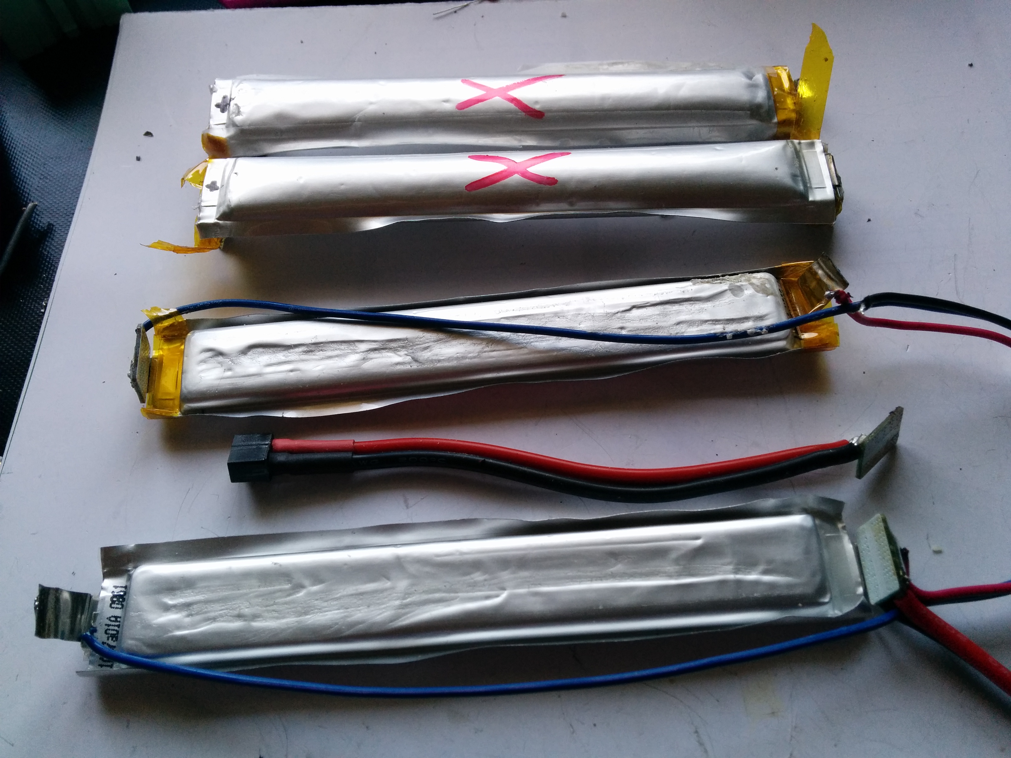
You can also see how the cells are joined via foil tabs at the end. Using a soldering iron, I heated up the solder on the joints, adding a little of my own to assist with the heat transfer. With solder melted, I simply pulled the cells apart. The end result was 4 cells, two good and two bad. The ones marked with a red X are the bad cells. You can see the extra puffiness in both of them in comparison to the good cells. In the bottom cell, you can see the board connecting the balance plug and main battery connector (a mini deans in this case) is left in place. This was deliberate as it reduced the number of extra solder joints to be done on the new battery and it would only have been a replication of the existing connections anyways.

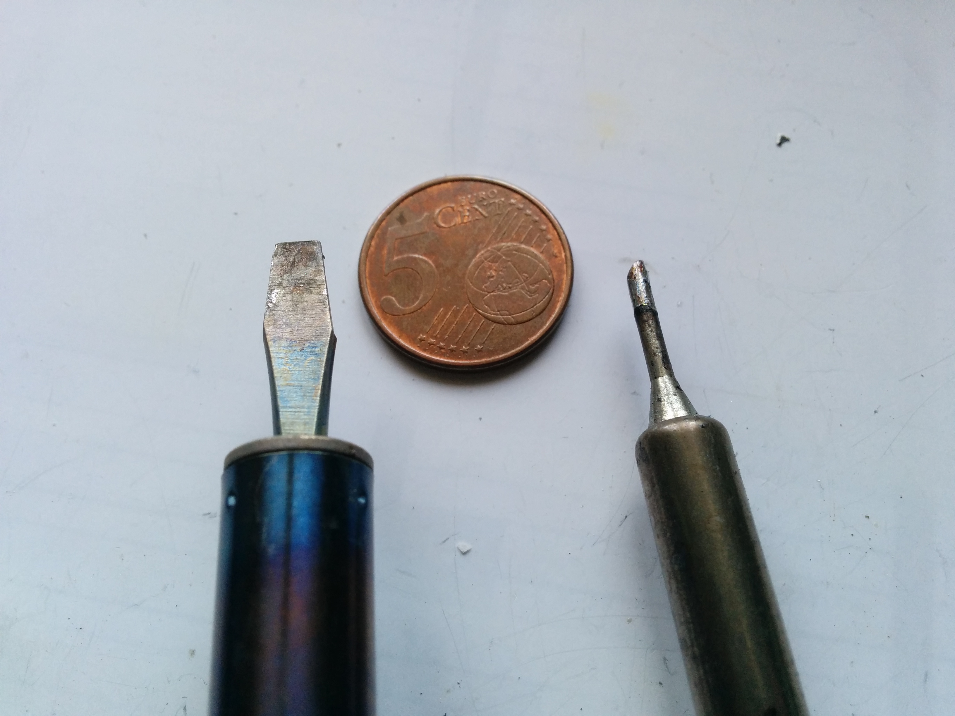
One thing to note when soldering batteries is the need to avoid heating the cells up. When working with lipo batteries, this is especially important. The technique used in industry is to use a spot welder on the battery tabs. That allows them to place a large amount of heat for a short amount of time thereby minimizing the chance of heat transfer into the cell itself. We can use a similar technique by using a soldering with a large head and by using a high temp ~ 500C. This is in contrast to the usual electronics soldering technique of smaller heads and a lower temp. You can see the difference in head size above, between the normal electronics soldering iron on the left and the larger iron on the right.
The technique is to allow the iron to come up to temperature, then place it on the solder joint. Feed in some new solder as this will help the spread of the heat throughout the joint. Once the solder has melted, remove the cell whilst simultaneously removing the soldering iron. This process should only take 2 seconds at most so do not leave the soldering iron in contact for long. You will also need to keep an eye on the temperature of the cell as the heat will damage it or possibly cause a fire.
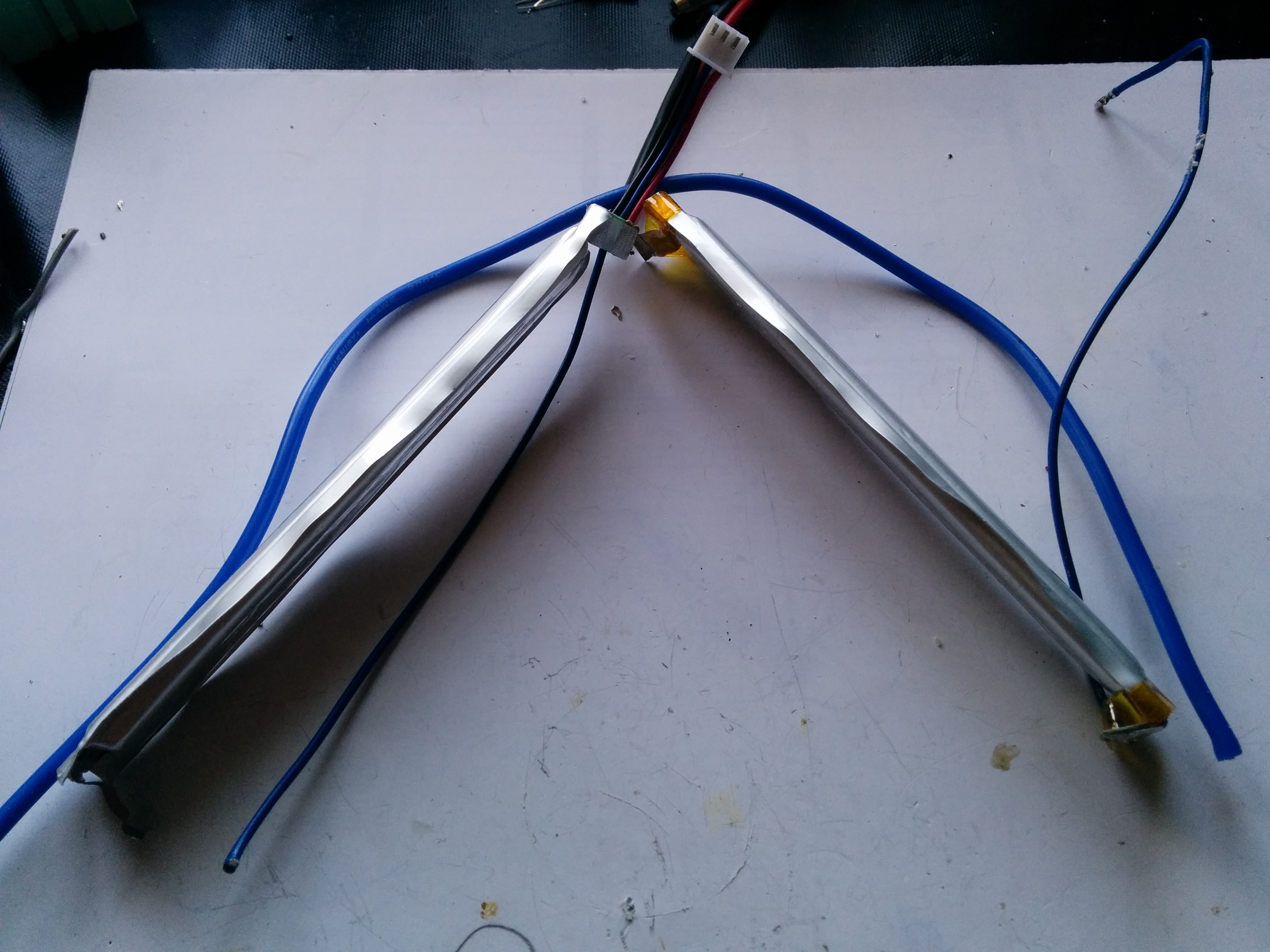
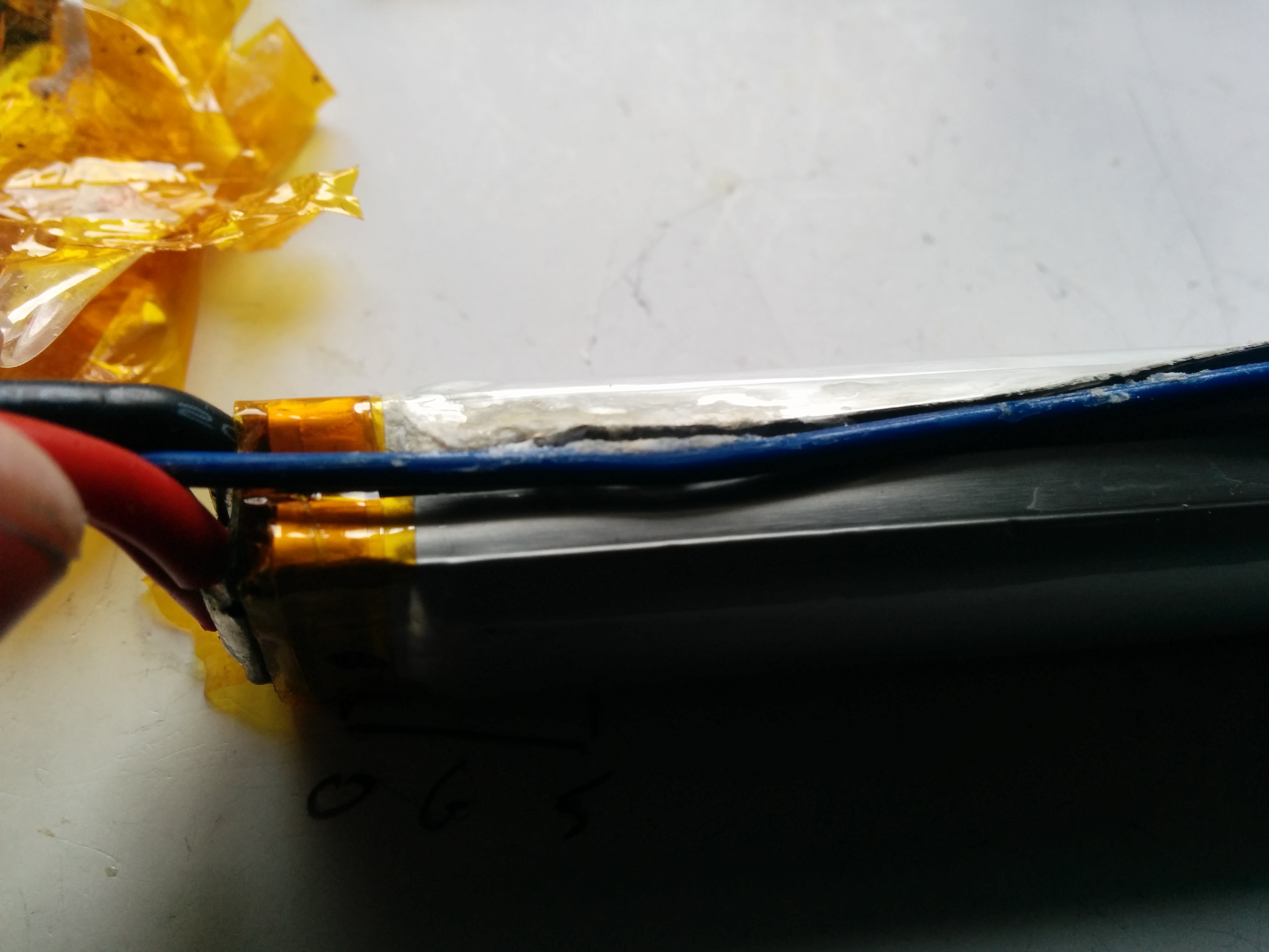
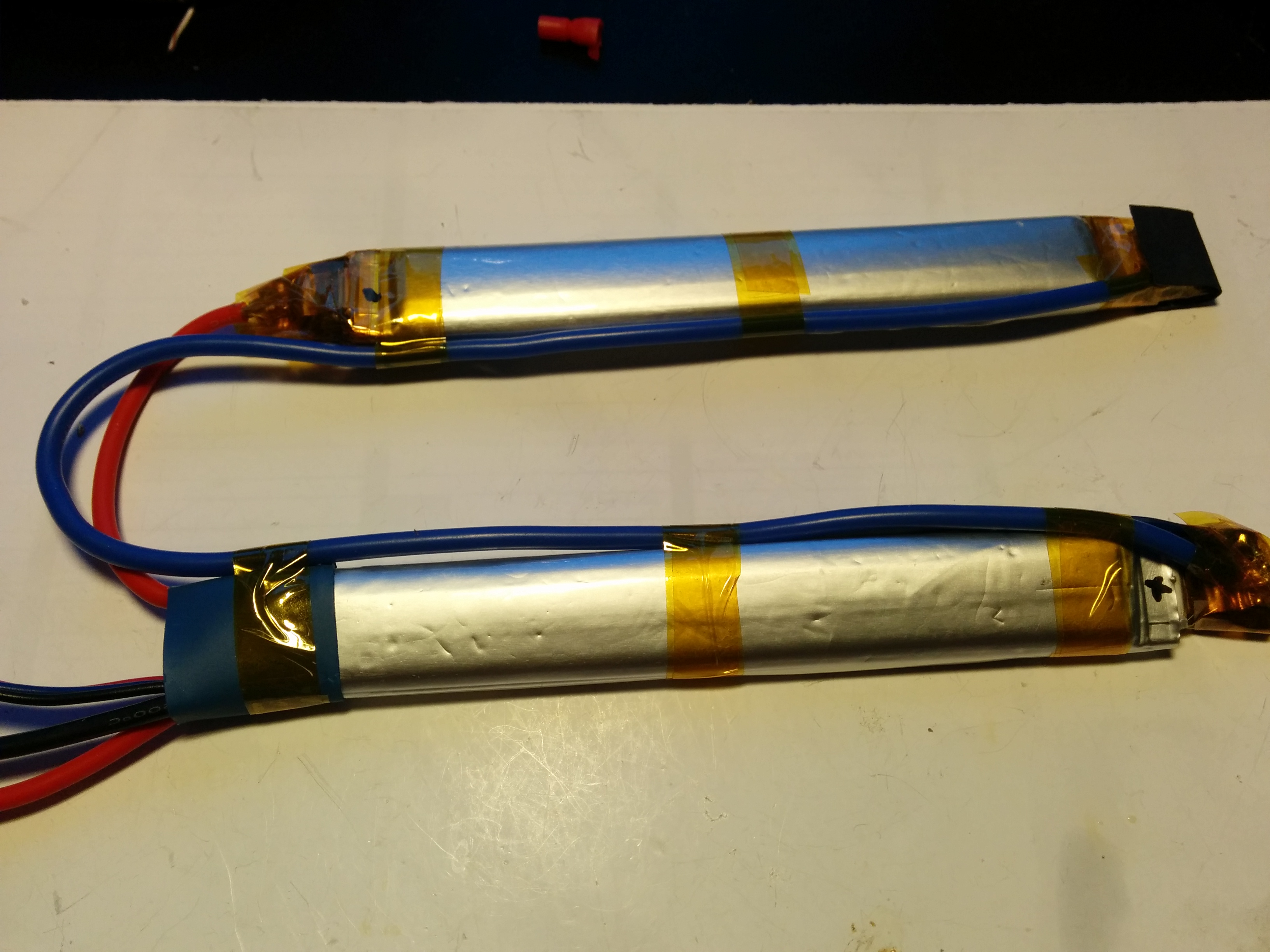
The battery I was creating was in the nunchuck style as it was to go into a tight space on the gun. Normally in a two cell lipo you would connect the cells directly end to end, but with the nunchuck style, a separate wire is required to run between the two. In the first picture above, you can see the thick blue wire which will join the negative of the right hand cell to the positive of the left hand cell. The wire use is 14 AWG to ensure it has the current carrying capacity – if you use a thin wire, it will heat up with the high current. If you are lucky it will just wear out……if unlucky it will cause a fire…..Can you see a running theme here regarding fire! 🙂
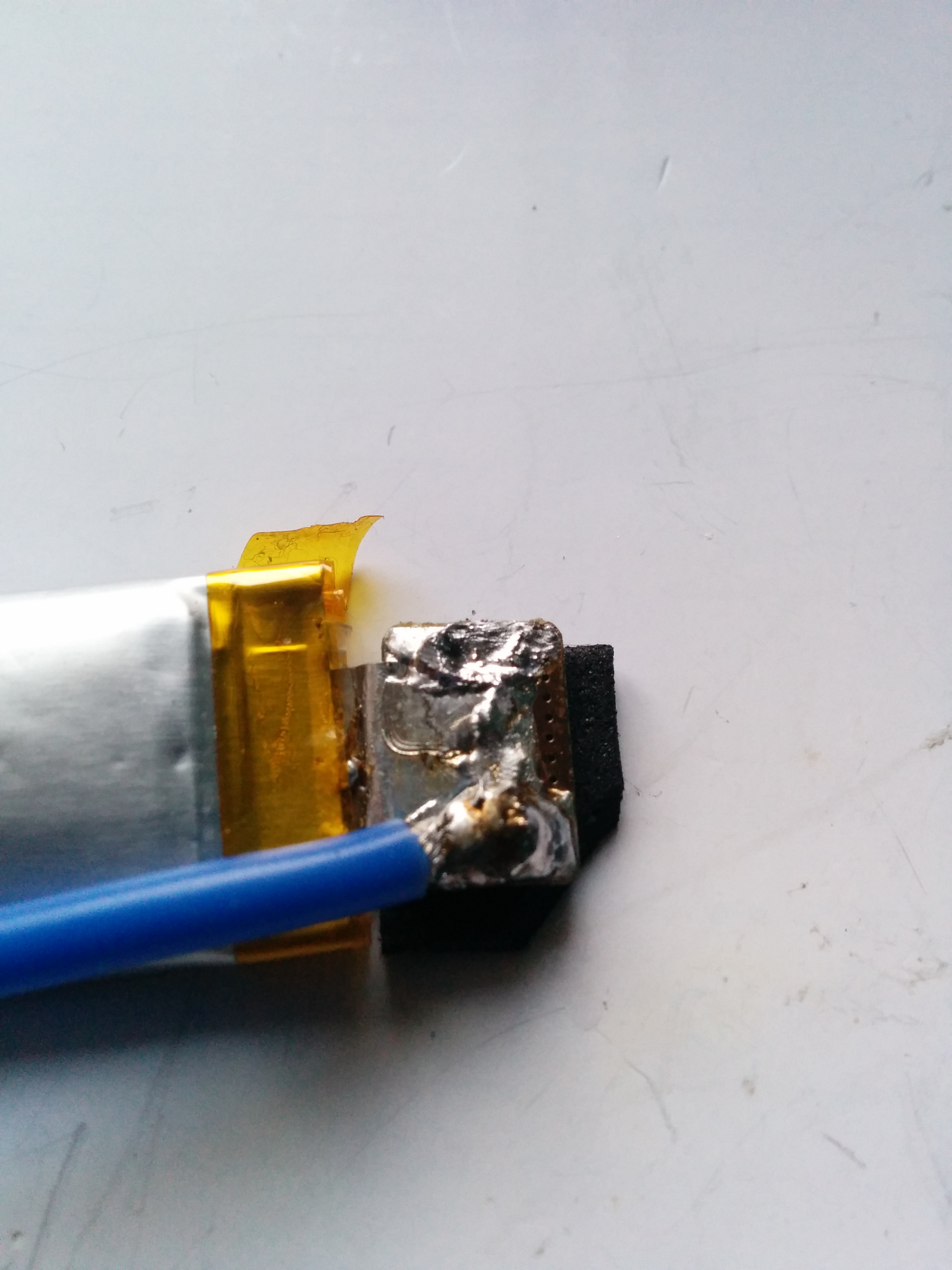
The thin blue wire on the left is coming from the balance plug. This will be extended down to end of the battery and it is important to keep this as a balance plug is necessary to maintain a healthy battery pack. In the right hand picture, you can see where the two wires have been soldered on to the tabs of the cells. I chose to flatten out the tabs to make it easier to solder onto, but this would latter come back to bite me when fitting the battery.
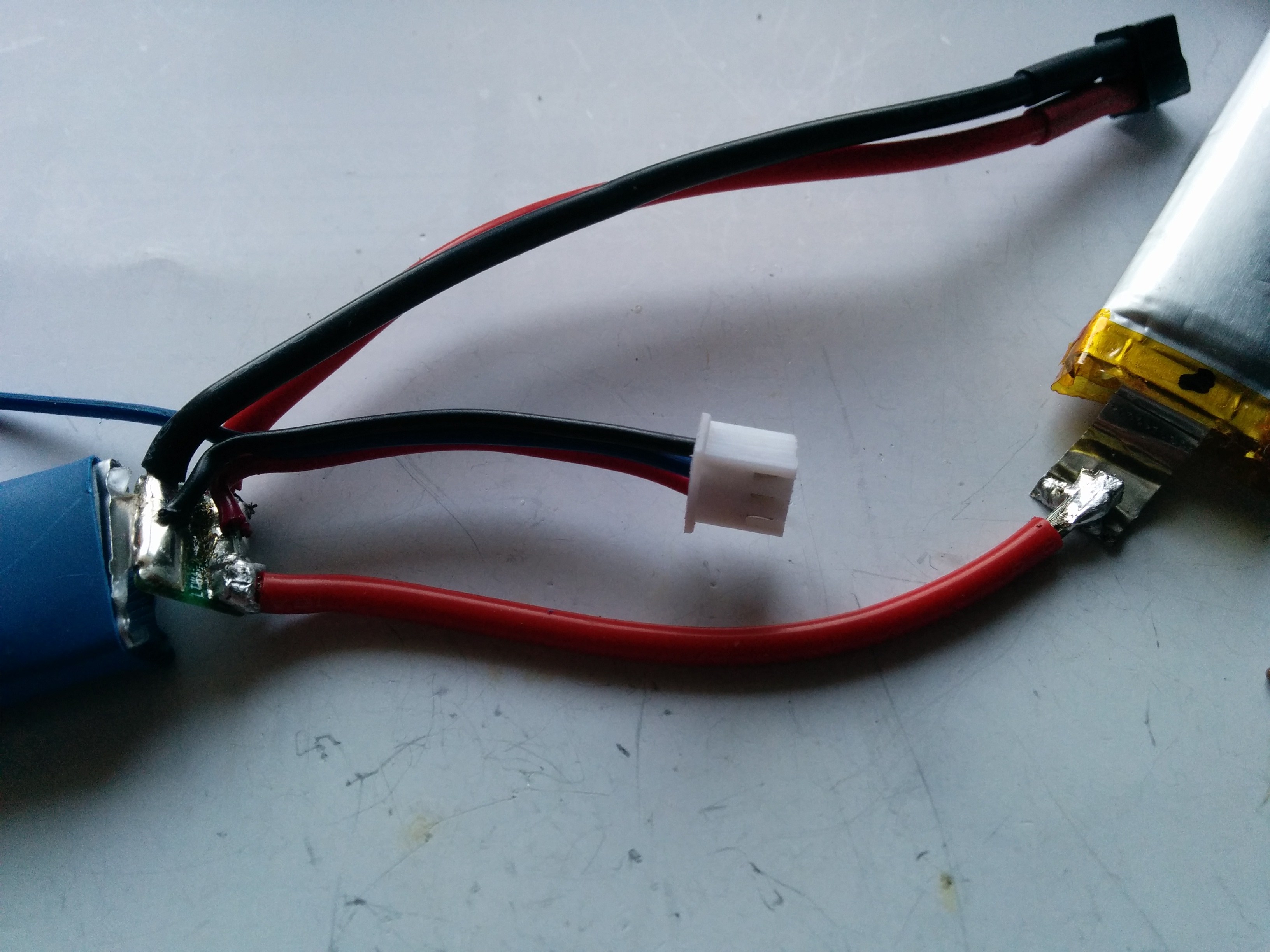
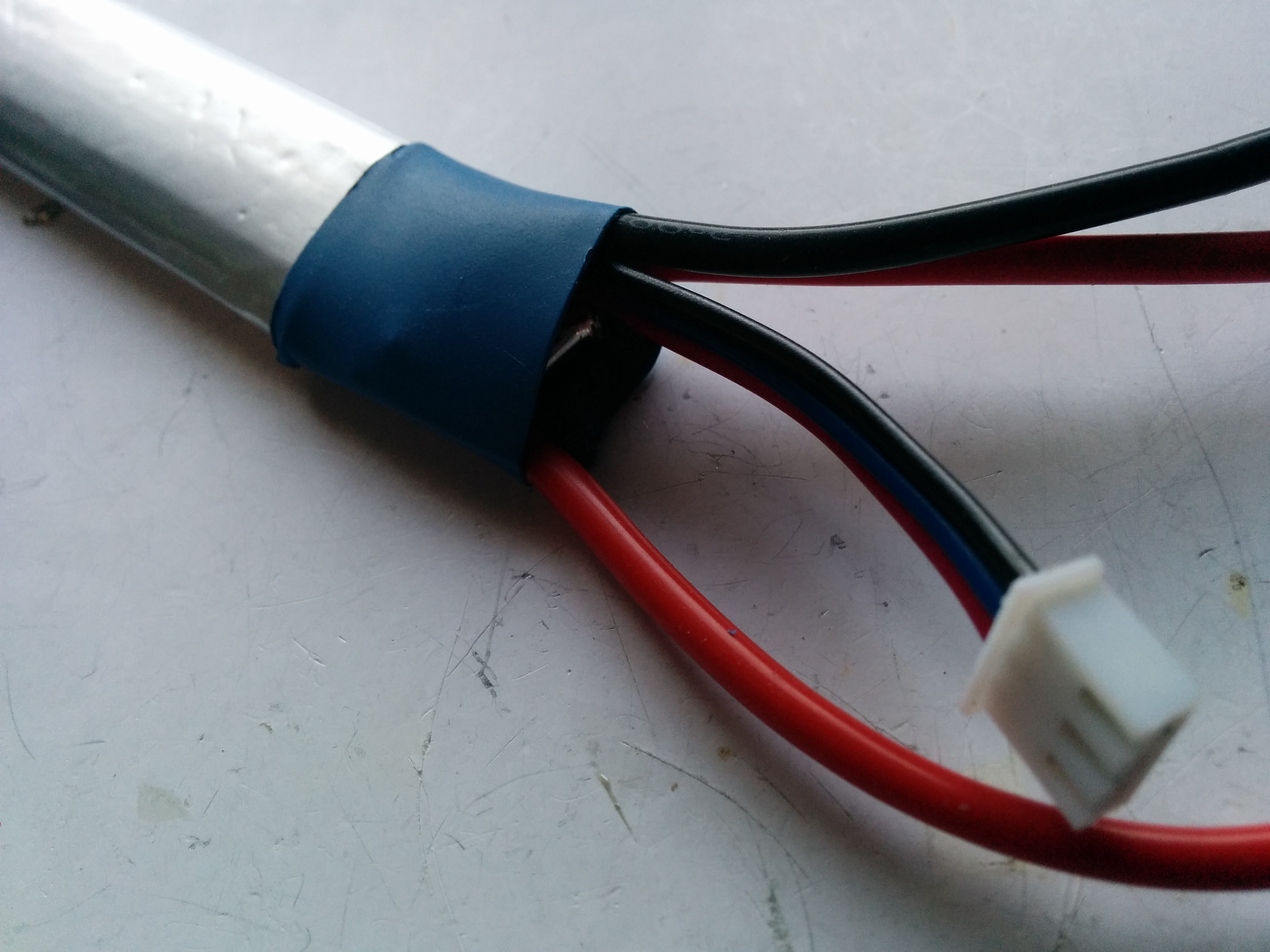
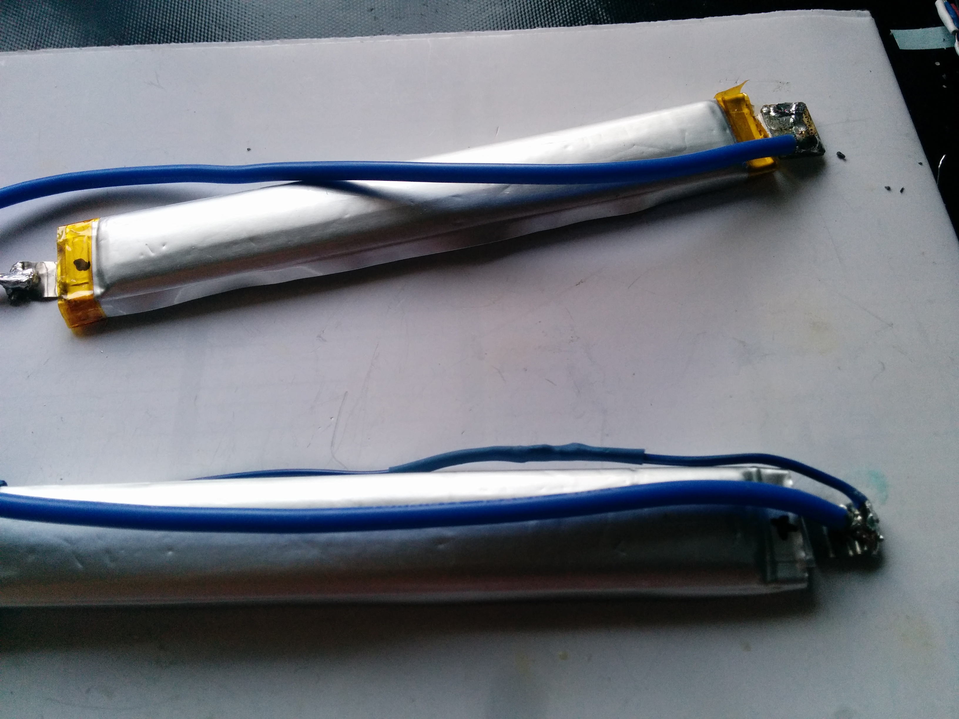
I also extended the connection from one cell to the other to allow for extra flexibility when inserting the battery in the gun. I also added some heatshrink to cover the main connections, and I later added some hot glue for further moisture protection.
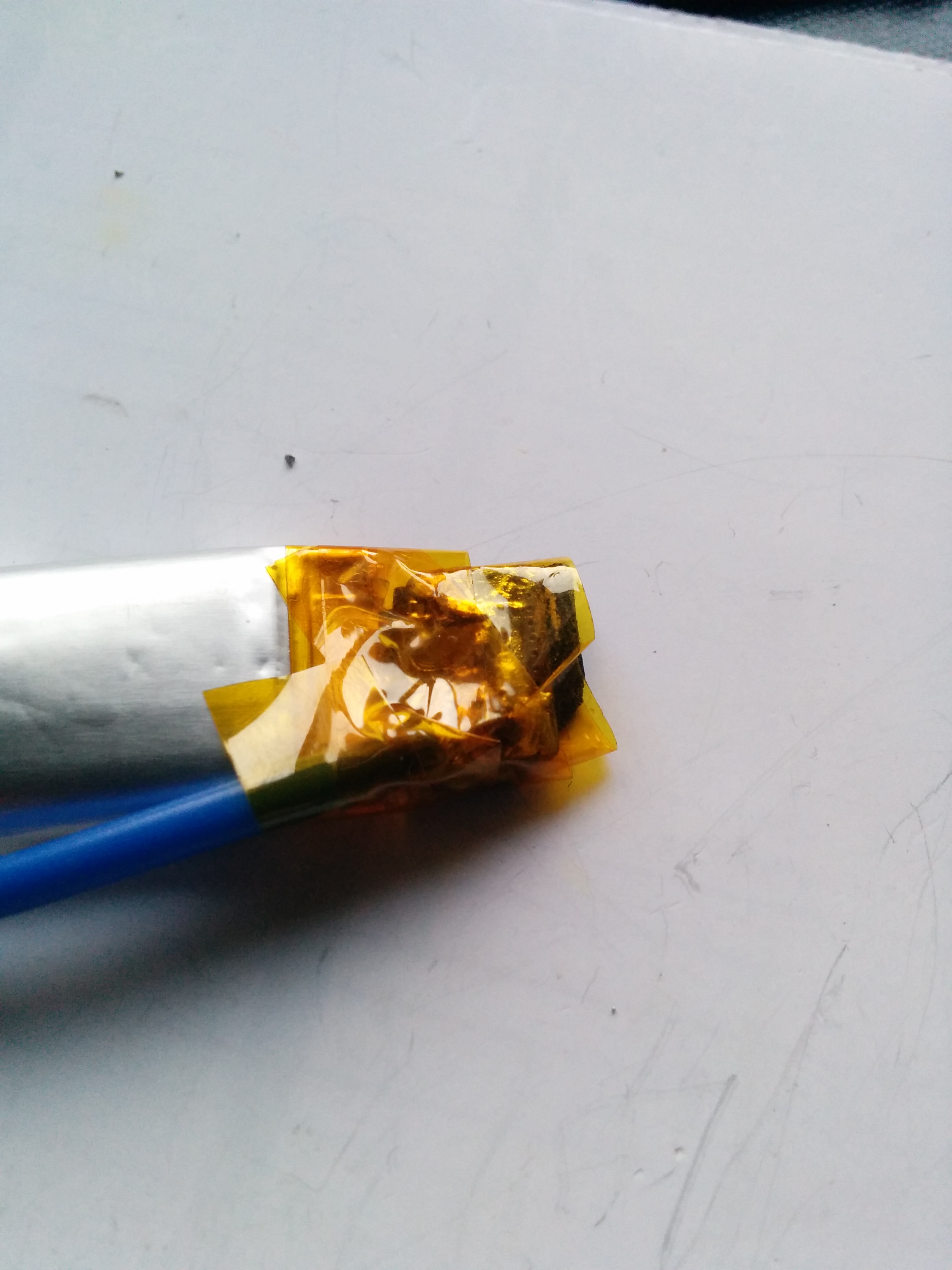
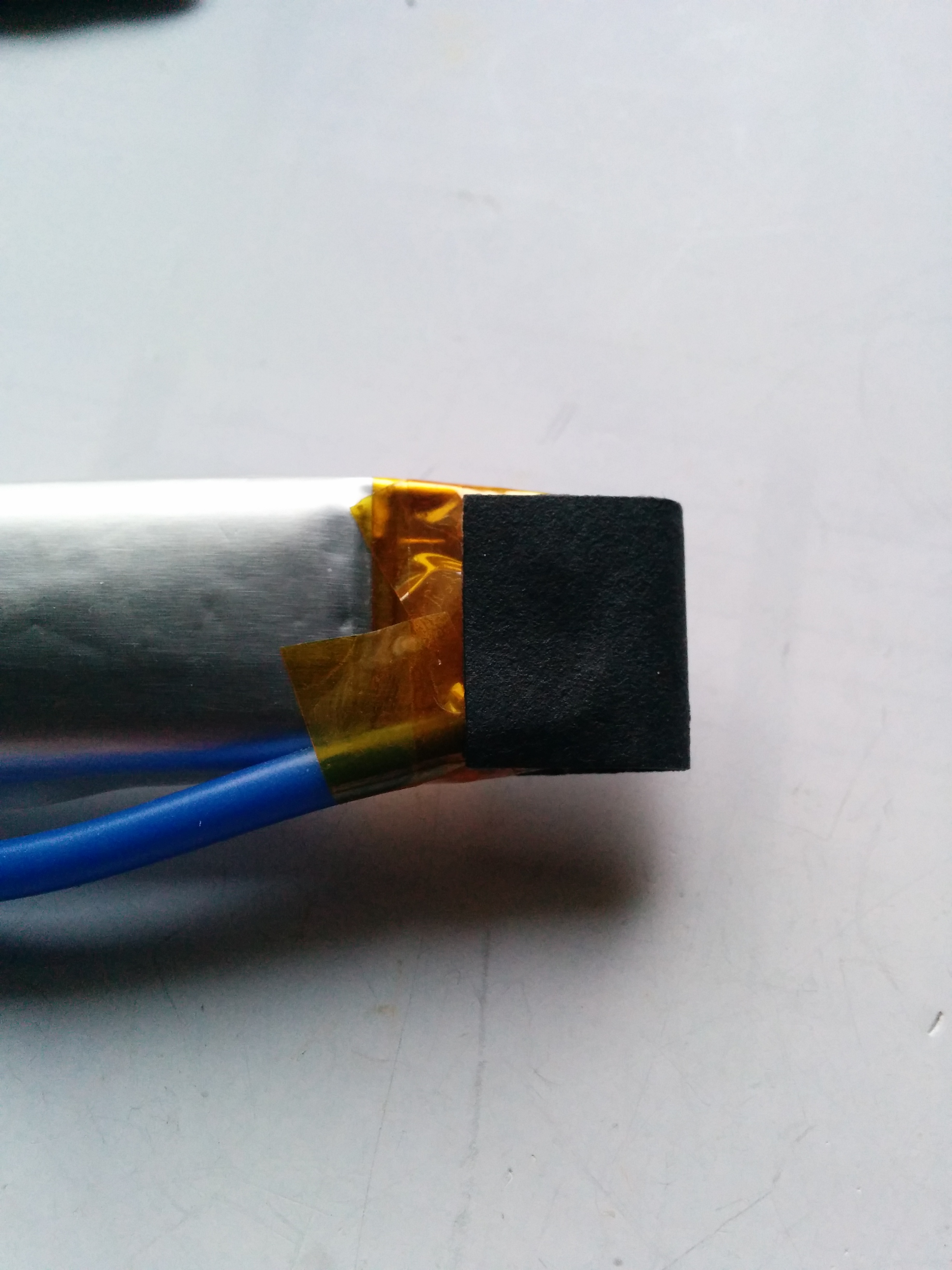
I used some foam padding which was removed during the teardown of the battery to give a little protection to the exposed tabs before wrapping the ends in new kapton tape. If you don’t have kapton tape, you could use insulation tape. I then replaced the thick paper on the ends and added some hot glue for further protection.
All done! I wrapped some more kapton around the cells and wire to keep it neat
However, on putting the battery in the gun, I realised that I had made each half of the nunchuk too long and it would not fit in! I had miscalculated and had been working off the assumption that the handguard when the battery went was all hollow, and also that a battery I was using for size had the correct length. I was wrong on both counts! I had planned to put some more heatshrink over the cells, but I am glad now that I didn’t as it gives me a chance to alter the soldering to shorten the connections and therefore the entire cell length.
When I will get around to do that is a different story!