Greetings from Kilnettle – Part 3

Having tested and placed the hall effect sensor, the next stage was to come up with an algorithm to detect the movement of the roll of tape, and to then calculate the amount of tape used.

In the episode, there are 3 phrases used (after more careful watching, there are four phrases) one each for “1 inch of sticky tape”, “2 inches of sticky tape” and “3 inches of sticky tape” (I got these lengths wrong too!). Based on this, I wanted to classify each tape usage into one of these three lengths and then play the appropriate phrase.

0 to 1 inch -> play 1 inch clip

1 to 2 inches -> play 2 inches clip

2 inches and above -> play 3 inches clip

My method of playback was going to be via a nifty module that plays back .wav and .ad4 stored on a micro SD card. The WTV020SD is readily available on ebay and is pretty cheap. There is a good library available for its use with an arduino, although it can also be used as a standalone player. The one downside, is that it requires 3.3V which means adding another regulator into the circuit if not natively available. Hooking it up to the arduino is pretty easy and I used a duemilanove as my development board and so used the 3.3V output from that to power the module during the development.

I fleshed out my algorithm idea on the whiteboard and drew up a circuit block diagram to help with the planning. You can see the picture below of the whiteboard stage, but please note the algorithm changed in the actual coding. Converting from pseudo code to actual code went pretty well considering it had been a while since I had done any programming on the arduino.


Before diving into the main program itself, I broke out some of the steps into separate chunks to test those first. By breaking the process into stages, it enabled me to simplify testing and identify quirks as there were some issues reported in the library’s thread on the arduino forum. It also allows for a more modular design in terms of approach.

First was to test the playback of the episode phrases. Using the scripts book, I had a good idea of the rough location of the phrases. I then used youtube as a source for the episode audio. I would have used my brother’s dvd boxset but it was with him out of the country!

I used an add-on for firefox to scrape out the audio as an mp3, then I converted the mp3 to wav using Audacity. I used a tool from 4D that converts .wav to .ad4. The tool is available for download on their Somo-14D page as it seems to be based off the same base chip as the WTV020. The files must be numbered 0000.ad4, 0001.ad4 and so on. Once converted, I copied them to the root of a an old 64MB microSD and placed the card in the WTV020.

The library comes with an example “sketch” so I used this to test the playback of the audio clips. There was a slight issue with the playVoice call as the toggling of the busy pin was not reliable. This was noted in the library thread with some fixes noted by others but even with those fixes applied, i was still having issues with the playback. Instead I chose to go with the asyncPlayVoice call which uses the delay() call to allocate the length of time to play the clip. Given I knew the length of each clip, this wasn’t a big deal.

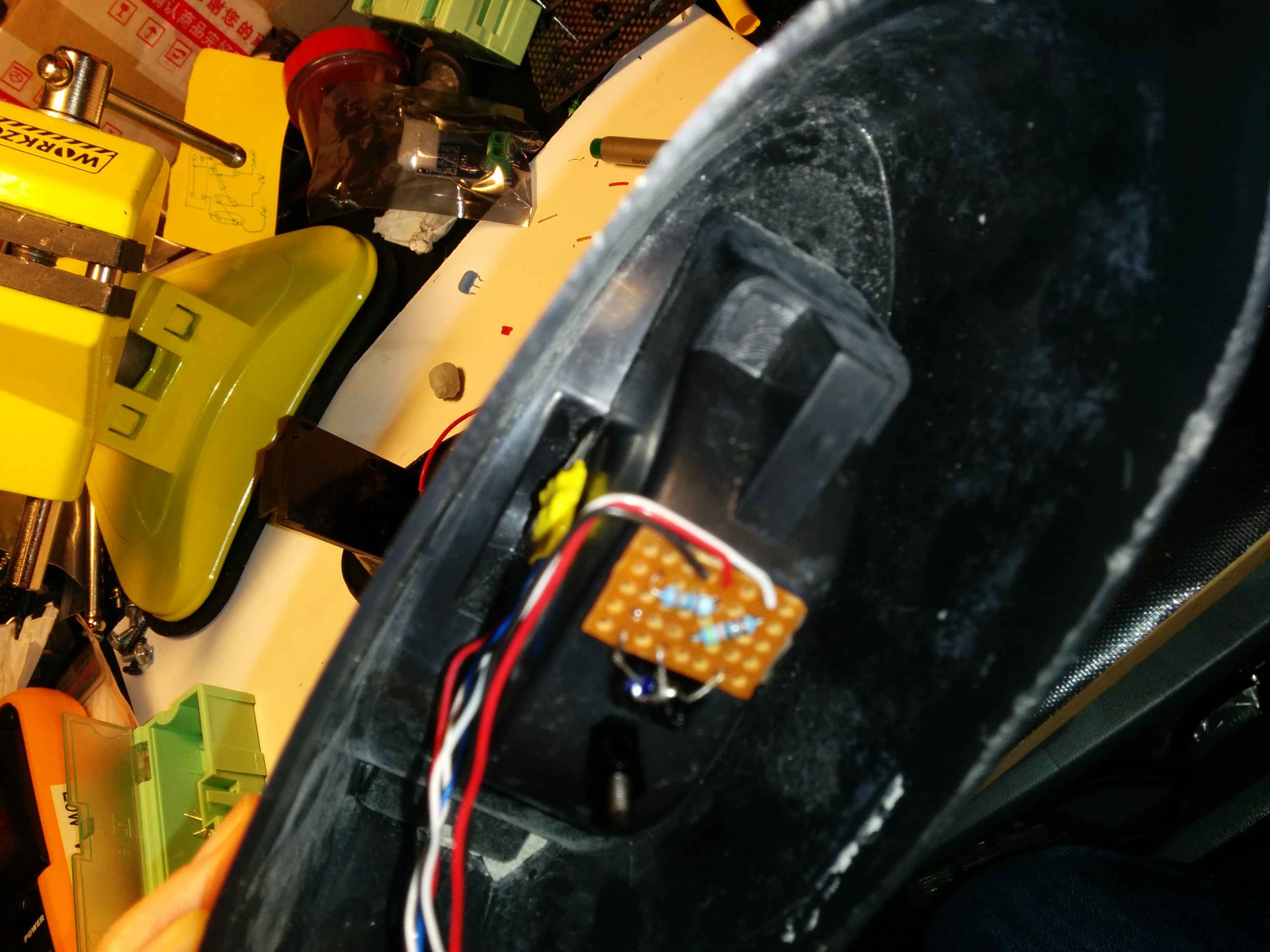
Using some buttons, I rigged up a circuit to trigger each clip based off a button press, i.e. press button 1 to play clip 1 etc. This worked well enough so I expanded to trigger off the hall effect sensor. I was using an extra hall sensor just plugged into the breadboard so I just added some code to read the value of the sensor and if it fell above 700 to play a sound clip. Again, this worked well enough so I was now happy I could trigger the playback of a desired clip as required.

Next up – the implementation of the logic for determining the length of tape used.


Greetings from Kilnettle – Part 2

After the trial of the infrared sensor, the next test was based on using a Hall Effect sensor. In this case an Allegro A1302 which is a pretty common hfe sensor. I got mine from Tayda Electronics which are a great source of “jellybean” parts.

I wanted to put the sensor on the inside of the dispenser so as to hide it from view so the first test was to see if the sensor was sensitive enough to pickup the magnet through the plastic of the dispenser. Again, I used analog read on the arduino but in this case the sensor requires no extra circuitry apart from 5v, Gnd and the output pin connected to analog 1. Instead of putting the sensor inside the dispenser, I left it on the breadboard and used the base I had removed from dispenser to simulate the dispenser wall.

The first magnets I used were some 6×2 mm ones which required that they were pushed up right against the dispenser wall to be detected. I’m not sure of the “N” rating as they were some ebay cheapo’s.

I then swapped to 4×2 mm N52 which worked a lot better. For the initial testing, I simply taped the magnets in placed but then swapped to using blu-tack for the actual installation. This would allow for the magnets to be moved to the next roll of tape once the current roll runs out – I do plan for this to be usable on a daily basis and not just a show piece!

As you can see from the picture, the magnets are inserted at equal spacings around the roll. I tried with three magnets but found that there were “dead” zones where the sensor value did not change. Also, as the magnets are side on to the sensor, there is a possible improvement to be gained by rotating them 90° so that the North or South pole is facing the sensor. As I didn’t have any smaller magnets, I stuck with the magnets as they were as there was enough of a variance in testing.

Satisfied with testing I decided to wire up the A1302. The downside of these sensors is that they can be a little sensitive to heat and I burnt out my first one as I applied the heat for too long in attaching the wires to the sensor. It still gave out values that corresponded to magnet proximity but the magnet had to be touching the sensor for any kind of change in result.

Not wanting to repeat the mistake, using a 3×3 piece of stripboard, I added the wires on one side first, then added the sensor. By placing the wires first, they acted as a heatsink when adding the sensor and so drew away any excess heat. If I was to place the sensor first and then the wires, the sensor would be subjected to extra heat as I was soldering the wires. As it was the wire to hand, I went for solid core but should really have used stranded wire to allow for greater flexibility when doing final assembly.

Once assembled, some heatshrink was used to seal it up and provide a nice surface for the “superglue” to adhere to.  Using the tape to hold the sensor in place temporarily, I optimised the placement to get the greatest range of values from the output pin. Once I was happy with the placement, I used some cheap superglue to hold it in place. The sensor now gave values ranging from 490 to 521 as the roll was spun.

A1302 can just be seen tucked away with the board covered in yellow heatshrink. The sensor itself was left exposed to avoid the addition of another medium to "sense" through.

A1302 can just be seen tucked away with the board covered in yellow heatshrink. The sensor itself was left exposed to avoid the addition of another medium to “sense” through. Picture was taken at a later stage in the build – the stripboard with resistors was not in place at the build point being described

Next step was to come up with the algorithm to detect and calculate the length for the removal of tape.

Greetings from Kilnettle

This was a project that I made for my brother who is a massive Father Ted fan. (Apologies for not having photos for every step and some are taken at a different stage in the build)

In the episode entitled, Flight into Terror, Dougal buys a tape dispenser in the duty free whilst they are travelling back from the fictional pilgrimage of Kilnettle. The tape dispenser, tells you how much tape you have used as you can see in the video below (first usage is at about 4:01 into the video):

For years, my brother has been after one of these and I finally got around to making him one. It measures the tape pulled and plays back clips from the show that correspond to the length. It also has a bonus feature which I shall reveal in a future post!

I bought two cheap dispensers that were on sale in Aldi – one to take apart as a test and one for the good model. (Also available from Tiger)It took a bit of work, but by sliding a screwdriver under the plastic base I was able to work my way around the base and take it off. It was held on by glue so I needed to be careful in a few spots.

Kilnettle002 Kilnettle009 Kilnettle010

After removing the base, I could see the weight to hold it steady during use was achieved by some cement. Luckily enough, this came out quite easily after a tap or two.

Kilnettle008

Looking inside I could see there was some good space inside and began to look at possible means of measuring the movement of the tape reel. My initial thoughts were to look at something like an optical line reader in conjunction with a black/white disk attached to the tape reel. However, this wasn’t very practical as the disk would stick to the side of the tape and I thought it may cause blockages. Also, as the tape was used up, the disk would have a greater diameter than the reel and I wasn’t happy with this aesthetically.

Next idea was to use some means of direct contact with the tape reel as it spins and feed that back to a rotary encoder. This was discounted due to the complexity of the mechanism required to maintain contact with the tape reel.

I had played around with infrared (IR) sensors in the past so decided to test out one that I had purchased with the idea of finding a project for at some stage. The TCRT5000 is a cheap IR sensor combo of an IR led and IR receiver in one small package. As the tape has a shiny surface, i wasn’t certain of the results I would get. If the reflectance didn’t change enough when the tape moved, it wouldn’t be a measurable parameter. I dremelled out a hole for the sensor and hooked it up the arduino using the analog read example. Disappointingly, it worked but not quite as expected.

Kilnettle013 Kilnettle012

It detected movement of the tape, but that was due to the tape reel moving vertically upwards as the tape was removed. It was a possible monitoring mechanism but was difficult to characterise. Plus, it was dependent on the users tape removal technique. My technique was to pull at a 45º angle which caused the movement upwards. If they pulled the tape horizontally outwards, there would be no change in height and therefore nothing to detect.

Onto a hall sensor…..in part 2 🙂