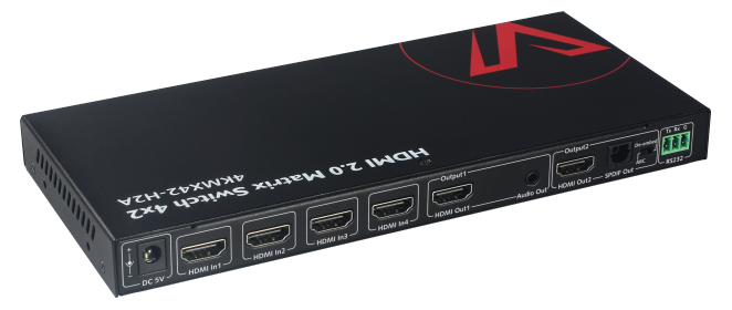
If you have a HDMI switch that looks like the one below, and are having problems with configuring it over serial, skip to the bottom for my solution. Please read on though if you want the full story!
I recently picked up a HDMI Matrix switch for our TV & Projector setup, specifically the AV Access 4KMX42-H2A.
The are a number of key features that I like:
- Infrared control – important later on for controlling with a Broadlink IR sender via HomeAssistant
- Supports 4K – we don’t have any 4K display kit right now but its nice to futureproof!
- Has 4 Inputs & 2 Outputs
- Can put 1 Input simultaneously to the 2 Outputs
- Can have 2 different Inputs on the 2 Outputs
- Supports a lot of higher end AV formats
- Dolby DTS-X, Dolby Atmos etc
Our plan was to use it to send the PlayStation, Roku, laptop or TV Receiver Box to the TV or the ceiling mounted projector as desired.
When I was setting it up however, I noticed that the remote control for the switch was activating some functions on our OSMega tv box – volume, menu items and channel changes. That makes it a bit awkward to use! Especially as you could end up changing something on the TV box without realising as you were swapping inputs/outputs on the HDMI switch. Even worse, when you adjusted the volume on the TV Box remote, it changed the input to the next one up!
However, another feature that is useful on the HDMI switch (that I thought might come in handy when purchasing!) is the ability to switch the IR codes. This means that the remote and HDMI switch can be configured to use a different set of IR codes to avoid conflicts with other IR controlled equipment – exactly the scenario we were in! And this is where the fun began…..
I knew from the manual (I assume you also read the manual before purchasing an item?…..) that the switch would need to be programmed over serial. Not a big deal – I have a good bit of experience in configuring devices over serial from Arduino to 3D Printers to networking equipment (Cisco switches and routers).
So I hooked up to the HDMI switch using the little 3 pin adapter supplied and a serial adapter I had and opened up my usual serial program, Putty. The api manual supplied the connection parameters below so I set them up in Putty, hit connect and tried the Get IR_SC command to see what IR mode the switch was in.
- Baud rate: 115200
- Databits: 8
- Parity: None
- Stop bits: 1
- Flow Control: None
No joy……
I have also used a few other programs over the years so I gave them a shot.
- ComTestSerial
- RealTerm
- Arduino Serial monitor
No joy……
Over the course of a few days I kept trying different combinations of serial adapters, cables, software, and swapping TX/RX pins. I tried all the various options and dropdowns in the programs, including different connection parameters as I had encountered incorrect details in manuals before. I even “ohm’d” the connection from serial adapter all the way to the port on the switch to prove I had no issues with the wiring.
No joy……
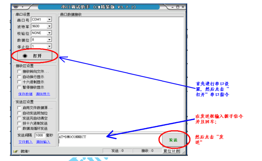
Looking further into the manual, it calls out a program called Serial Assist. Perhaps there is some secret sauce in there that would help? So I thought I would download that and try that out .
No joy…..
It was not to be found anywhere. I found some similarly named software called Serial Port Assistant but that was not it. The closest I found was a picture of it in this pdf for a radio receiver. Even with a version number to search for, I could not find a download anywhere.
So I contacted the vendor detailing what software I had tried and the settings I had used, and they confirmed that I was using the correct settings. But, that I would also need to enable CR/NL. These refer to Carriage Return and New Line which are very similar in function but slightly different in definition. There is a good historical explanation here with reference to their origin from manual typewriters.
So I set up two serial adapters with different software, planning to show exactly what I was using, in the hope that they could spot something that I was missing out on. First I found out that my cheap usb serial adapters were not capable of communicating in the higher baud rates! 9600 was fine, but 115200 was too high. Luckily, I had two higher quality adapters from Lindy & Startech that were compliant.
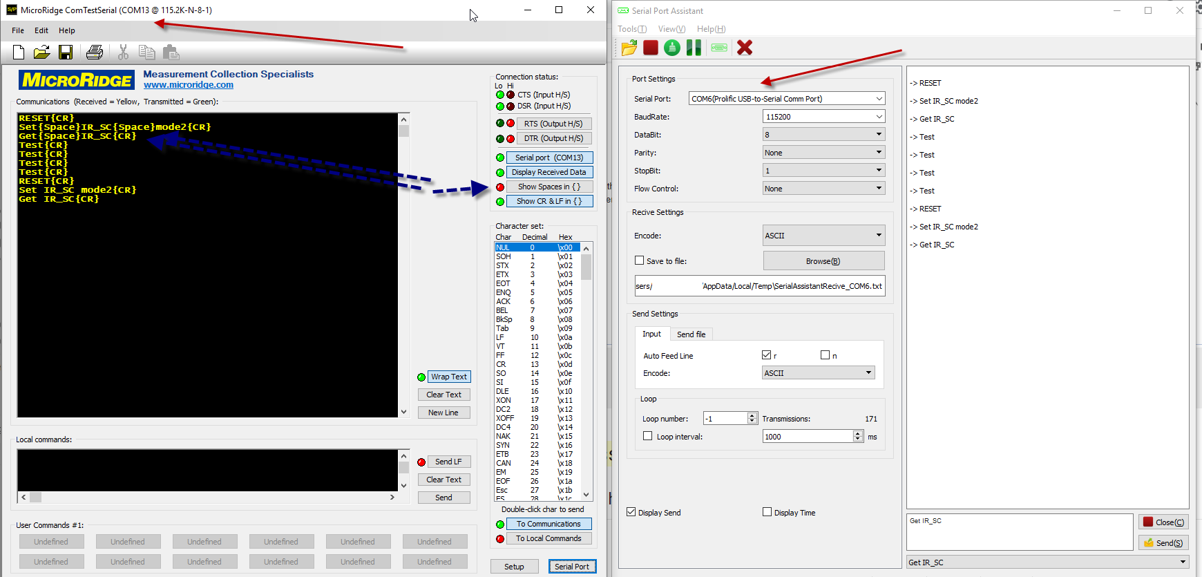
Here you can see I am sending the commands required from the Serial Port Assistant software on the left to the ComTestSerial on the right. The blue dotted arrows show the feature in the ComTestSerial to highlight spaces received in {}. Everything is being received correctly so I know my configs and cables are working! I hook up to the HDMI switch with confidence knowing that I have a working serial connection……
No joy…….
I sent that same picture to the vendor and they told me to tick the “n” box in the send settings of the Serial Port Assistant. I’m pretty sure I had done that already in one of my many, many attempts to get it working but I didn’t have it enabled in the picture I had sent them. So I gave that a shot.
There was joy!
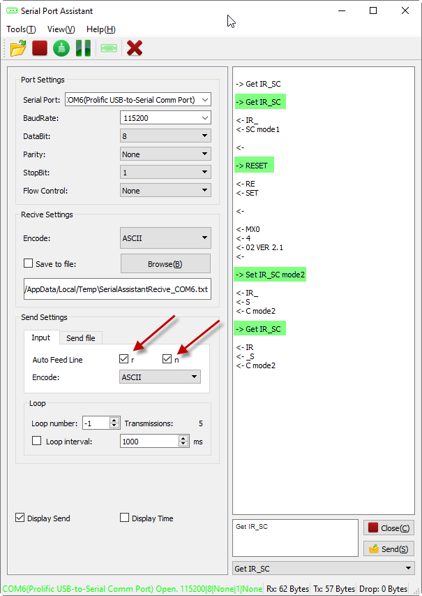
The TLDR:
The two boxes I needed to enable were the “r” and the “n” in Serial Port Assistant. I have highlighted in green the commands I was sending. You can see the return data from the HDMI switch was not processed correctly as it kept putting in new lines where there should be none, but it worked! I had now enabled mode 2 on the HDMI switch!
I wasn’t quite finished though. I still needed to configure the remote to use the Mode 2 codes. Thats the easy part though, there is a small push button on the remote to switch to using Mode 2 codes.
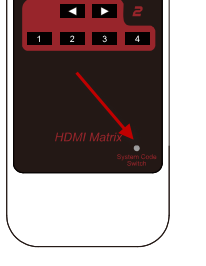
If you have already pressed that button on the remote and you wish to return to Mode 1, then simply pull the battery for a few mins and it will default back to Mode 1. Also something to remember when changing the battery!
Got there in the end, but I’m still not sure why the manufacturer doesn’t have a an easier method to change between Mode 1 and Mode 2 on the HDMI switch itself. A physical toggle switch would be nice but even some key combo from the remote would be a good alternative. Or even a download link to a specific serial term program and a set of instructions for that software.