After the trial of the infrared sensor, the next test was based on using a Hall Effect sensor. In this case an Allegro A1302 which is a pretty common hfe sensor. I got mine from Tayda Electronics which are a great source of “jellybean” parts.
I wanted to put the sensor on the inside of the dispenser so as to hide it from view so the first test was to see if the sensor was sensitive enough to pickup the magnet through the plastic of the dispenser. Again, I used analog read on the arduino but in this case the sensor requires no extra circuitry apart from 5v, Gnd and the output pin connected to analog 1. Instead of putting the sensor inside the dispenser, I left it on the breadboard and used the base I had removed from dispenser to simulate the dispenser wall.
The first magnets I used were some 6×2 mm ones which required that they were pushed up right against the dispenser wall to be detected. I’m not sure of the “N” rating as they were some ebay cheapo’s.
I then swapped to 4×2 mm N52 which worked a lot better. For the initial testing, I simply taped the magnets in placed but then swapped to using blu-tack for the actual installation. This would allow for the magnets to be moved to the next roll of tape once the current roll runs out – I do plan for this to be usable on a daily basis and not just a show piece!
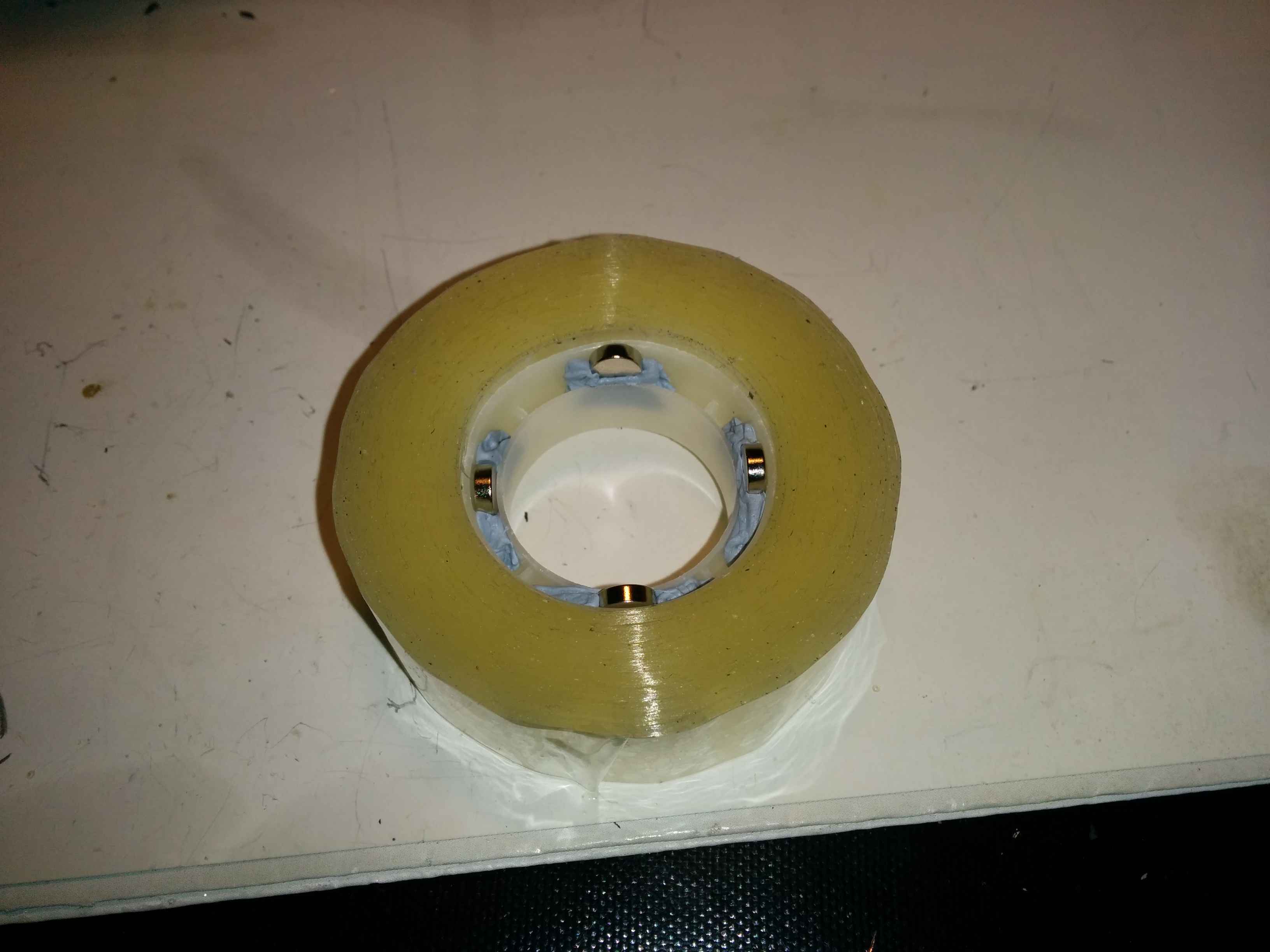
As you can see from the picture, the magnets are inserted at equal spacings around the roll. I tried with three magnets but found that there were “dead” zones where the sensor value did not change. Also, as the magnets are side on to the sensor, there is a possible improvement to be gained by rotating them 90° so that the North or South pole is facing the sensor. As I didn’t have any smaller magnets, I stuck with the magnets as they were as there was enough of a variance in testing.
Satisfied with testing I decided to wire up the A1302. The downside of these sensors is that they can be a little sensitive to heat and I burnt out my first one as I applied the heat for too long in attaching the wires to the sensor. It still gave out values that corresponded to magnet proximity but the magnet had to be touching the sensor for any kind of change in result.
Not wanting to repeat the mistake, using a 3×3 piece of stripboard, I added the wires on one side first, then added the sensor. By placing the wires first, they acted as a heatsink when adding the sensor and so drew away any excess heat. If I was to place the sensor first and then the wires, the sensor would be subjected to extra heat as I was soldering the wires. As it was the wire to hand, I went for solid core but should really have used stranded wire to allow for greater flexibility when doing final assembly.
Once assembled, some heatshrink was used to seal it up and provide a nice surface for the “superglue” to adhere to. Using the tape to hold the sensor in place temporarily, I optimised the placement to get the greatest range of values from the output pin. Once I was happy with the placement, I used some cheap superglue to hold it in place. The sensor now gave values ranging from 490 to 521 as the roll was spun.
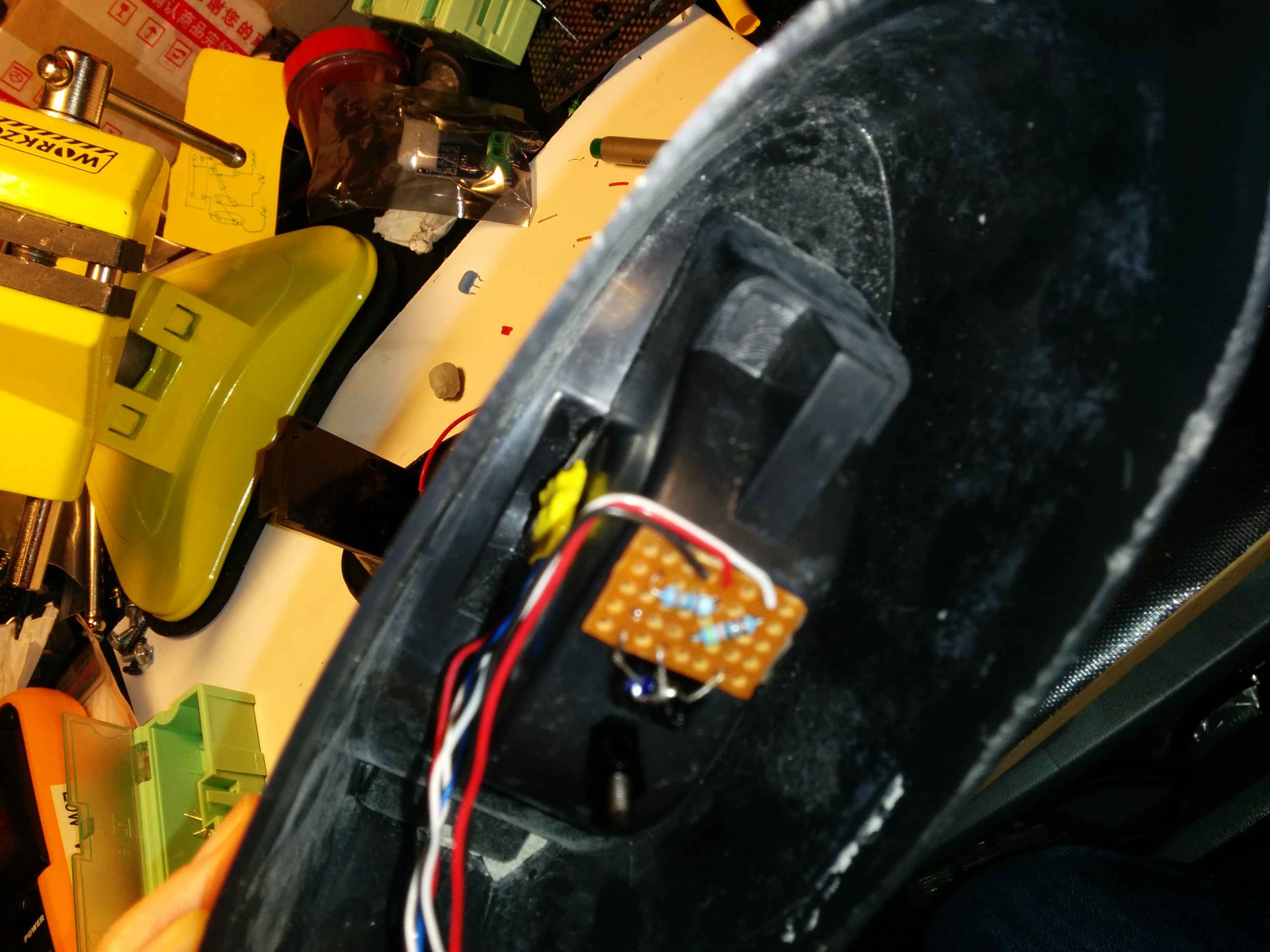
A1302 can just be seen tucked away with the board covered in yellow heatshrink. The sensor itself was left exposed to avoid the addition of another medium to “sense” through. Picture was taken at a later stage in the build – the stripboard with resistors was not in place at the build point being described
Next step was to come up with the algorithm to detect and calculate the length for the removal of tape.